3D Printing: Remote Direct Extruder with Flexible Drive Shaft and Worm Gear
I present a solution, that combines the principles of Direct-Drive and the Bowden Extruder of a regular 3D Printer. The project is open-source. All files are available for download below. All parts of the BOM are bulk goods, publicly available. You need a 3D-Printer and a screw-driver for the assembly.
You’ve probably heard this question before: „Direct Drive or Bowden Extruder ?“
Both System have its benefits. In my opinion, the direct drive is more reliable and exact in the extrusion of the material. The direct drive extruders are very heavy in general and therefore cannot be driven with high acceleration. The common stepper motors of size nema17 weight about 300g, which is slightly too much accelerated mass for the structure of a hypercube evolution. This is why I designed with the following extruder.
Description
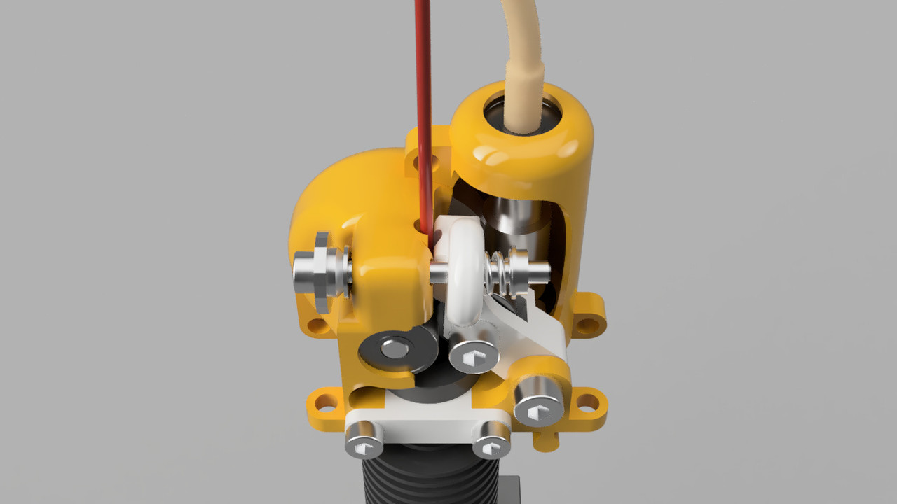
The presented solution gives a reliable way of printing direct, without a stepper motor on the extruder carriage. A flexible drive shaft is used to transfer the rotational movement of the stepper motor to the carriage. A worm gear reduces the rotational movement by 1:25 and a threaded gear converts the rotational movement in a linear motion, which drives the filament through the extruder underneath the gearbox.
Notes on the project
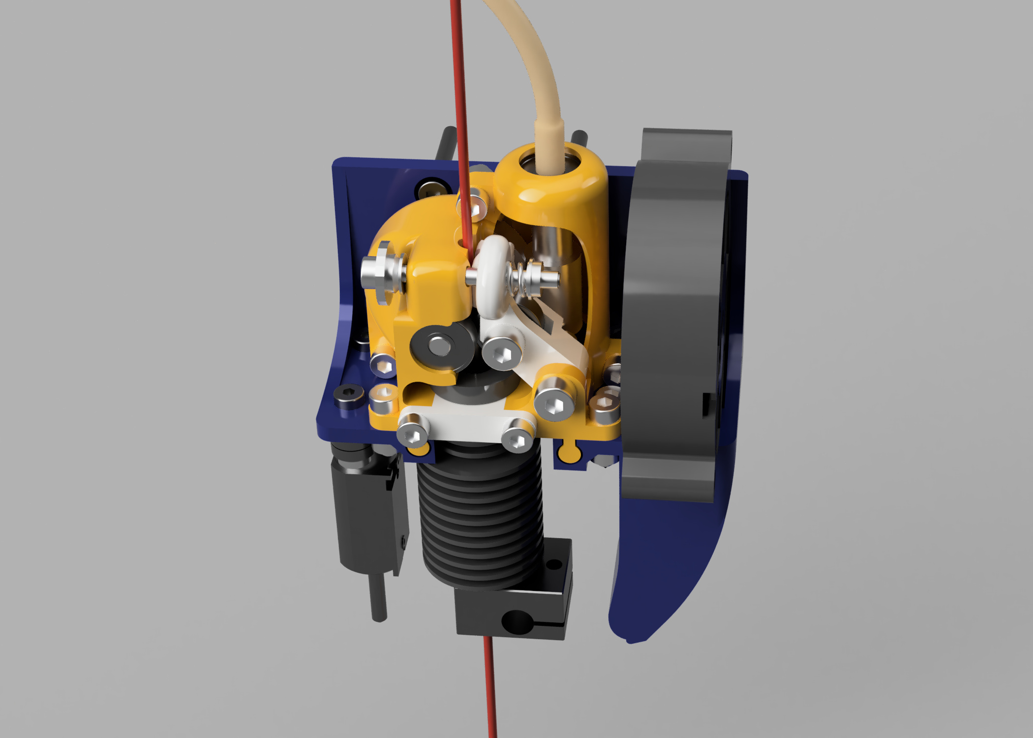
Drive shafts do not work exact. The drive shaft in the project has a translation shift twist of ± 45 percent. This is why its not recommended to drive your 3d printer directly with the drive shaft. I use a 1:25 reduction gear to eliminate the error. The setup works exact and reliable with this twist. The design of the gearbox itself is modular. The gearbox can be mounted on any other carriage by integrating the two nobs on the bottom side.
Notes on the print
The gearbox is designed to be lightweight and easy to print. You will need to use support material on the outside of the parts of the gearbox. The inside has to stay free of support material, because otherwise the remains of the removed support will interfere with the fit of bearings.
I tried to do a good job at the costs of the parts. All parts are manufactured in china and are available for a reasonable price at multiple stores or can be printed via FDM.
I recommend a step-up gearbox for the stepper motor of the extruder for high printing speeds. This feature will enable faster retraction speeds. OCD3D designed a printable solution here [0]
Constraints
Hypercube evo / Hypercube carriage (You can design your own version of the carriage with the .step-file in the download section)
suitable for both common filament diameters (1.75mm and 2.85mm)
Bill of Material (BOM)
- worm gear reduction, see [1]
- 604 bearing (x2), see [2]
- 695 bearing (x3), see [3]
- flexible drive shaft 4mm diameter [4]
- mk8 threaded gear (the next version will support the original mk7 too)
- Radial Fan
- M3 Screws and Nuts
- M4x16 Screw (x2)
- Screw of Heatbed [5]
Parts designed for FDM (Fused Deposition Molding aka 3D Printing)
- front and back-panel of the gearbox
- filament clamp
- hotend bracket
- fan duct
- carriage with distance holder for the BLTOUCH Proximity Sensor

The Project is under the Attribution-NonCommercial-ShareAlike 4.0 International (CC BY-NC-SA 4.0) License. This means you are free to copy the model or adapt it for non-commercial purposes.
[0] https://www.thingiverse.com/thing:2380353
[1] https://www.ebay.de/itm/Metall-Schneckenrad-Kunststoff-Untersetzungsgetriebe-Reduktion-Getriebe-Zubeh-HV/283840208648?hash=item421631df08:g:MdAAAOSwm4NbIPhA
[2] https://medias.schaeffler.com/medias/de!hp.ec.br/62?#62
[3] https://medias.schaeffler.com/medias/de!hp.ec.br.pr/S69..-2Z*S695-2Z
[4] direct link to aliexpress.com
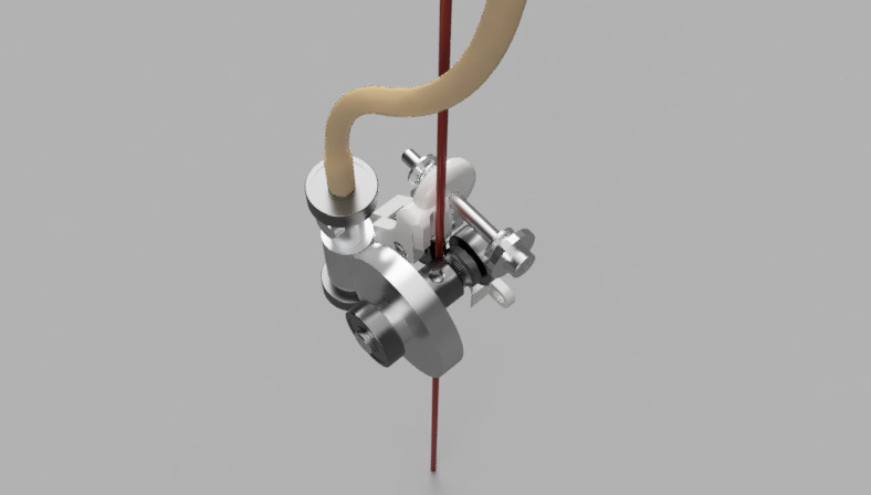
Some additional renders and photos of the concept


Update 2021-04
As a result of many tests, I recommend a step-up gearbox for the stepper motor of the extruder for higher printing speeds. A simple solution is a 1:3 step-up gearbox for the stepper motor, which is not sold in bulk. I will upload a printable design in some weeks.
This upgrade enables very high printing speeds. The overall speed is not limited by the extruder. My setup uses Nema 17 (17hs19-2004s) Motors for the XY-Axis, they skip steps at some point and therefore limit the printing speed. A perfect speed for the Hypercube Revolution setup will be around 130mm per Second, with a K-Factor of 0.02 or less.

Hi Dominik. Would this be suitable for a delta printer?
Hi Stu,
its definitely compatible with delta printers. It will probably create even better results with a delta printer, because you can clip the flexible drift shaft between the arms of the printer.
You would have to design your own connection to the carriage.
Please keep me updated, if you try to build it 😉
I am constantly looking online for tips that can facilitate me. Thank you!
Hi, sehr coole Idee! Gibt es von dem Projekt längerfristige Erfahrungswerte? Gibt es ein Video, dass den Extruder in Aktion zeigt? Gibt es eine Aufbauanleitung?
Grüße
Steffen
Hi Steffen,
indeed. According to my experience with the setup for at least 14 month, it works. The setup need some special care. I would use some chain lubricant for the worm gear, as it actually spins at around 300rpm and some grease for the 1:3 step-up gearbox. Other than that, it works continuously.
In this year, I would probably use a improved hot-end, e.g. the mosquito-hotend for better performance.
PS: I just found your reply in the spam of the site, sorry for the late reply.
Hi Steffen, I just added a little video. It shows the first version of the project in February 2020.
There is no instruction for the assembly and I think you wouldn’t need one. If you need additional instruction, just let me know.
Hey there,
I’m interested to attempt this project. However, I cannot open the ebay link for [1]. Could you provide another link to the items? Thanks!
Warm Regards,
Tim
Hi Tim,
here is a alternative shop for the worm gear set
https://www.ebay.de/sch/i.html?_from=R40&_trksid=m570.l1313&_nkw=294106015615&_sacat=0
Let me know, if you need some additional information.
PS: I just found your reply in the spam of the site, sorry for the late reply.